Posted: December 5, 2012
Systems analysis identifies how devices are used together – and may include testing of signals and software inside or between chips using sniffers, probing, data capture, or literature. Systems analysis, including software reverse engineering, is performed to identify evidence of use in support of patent licensing and litigation. It can also be used for competitive benchmarking purposes in the area of electronic devices. As an example of systems analysis, we looked at what happens during the handshake between an Apple iPhone and one of the chips inside the Apple Lightning to USB cable.
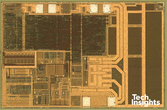
The first step is removing the plastic housing and decapsulating the silicon to better understand what is going on by cataloging the chips and passives. As a side note, in the electronics world, we need to redefine the meaning of a “cable” since Websters' dictionary description of “a wire or rope by which force is exerted to control or operate a mechanism” is no longer relevant. In this case, the Lightening to USB cable of today contains a number of chips and devices.
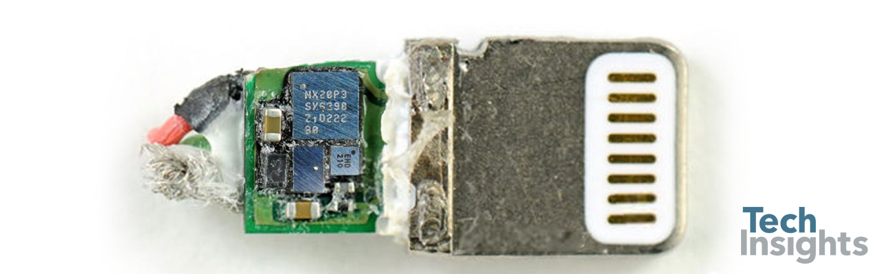
Inside the Apple Lightning Cable
Four total die were found in the cable:
- NXP SP3D2
- STMicroelectronics USB2A
- Texas Instruments BQ2025
- Unknown manufacturer with markings identified as 4S (functionality is known)
TI BQ2025
The TI BQ2025 has an important communication interface. So this investigation will look at one specific step that happens when you plug the cable into a phone.
Considering some of the speculation on the web, we initially considered that the mystery chip could contain some security, so to test this theory, we investigated the TI BQ2025 by looking at the initial handshake. From this we see no evidence of any form of security at this stage of communication. To better understand this device, we are actually completing a circuit analysis report of some key analog blocks on this high volume part by TI – but that is a circuit analysis, and potentially the subject of a different blog.
First, let’s take a look at how we did our analysis.
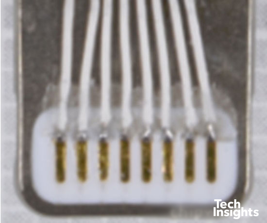
Test Harness
Test Harness
The figure shows our test leads soldered to the pins of a Lightning cable. From here, the leads go to a test header, and finally to a logic analyzer. Soldering these is especially tricky because the white plastic seen around the pins has a much lower melting point than solder. It is easily transformed into a bubbling mess if you don’t work quickly!
Electrical Signals
Electrical Signals
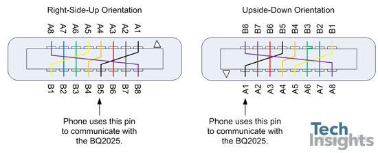
The BQ2025’s one data pin is connected to two Lightning cable pins. Why two? Recall that the Lightning cable is designed to work no matter which way it is inserted into the phone (USB anyone?). Some may call it lazy to not have to think when plugging something in, but we feel that it is a subtle improvement in usability that shows attention to detail.
The figure below shows the Lightning cable in two orientations (there’s a little white triangle on the diagram to help you visualize the rotation). The coloured lines indicate electrically equivalent pins. We know from our circuit board analysis that the BQ2025 connects to the black signal. Effectively then, the BQ2025 is connected to two Lightning cable pins. We’ve labelled them A1 and B5.
The phone itself only monitors the bottom row of pins. If the user has inserted the cable right-side-up, the phone needs to use the pin, which is fifth from the left, to communicate with the BQ2025. That’s where the black signal is. Furthermore, if the user has inserted the cable upside-down (or is it right-side-up?), the phone needs to use the left-most pin.
Orientation Discovery
Orientation Discovery
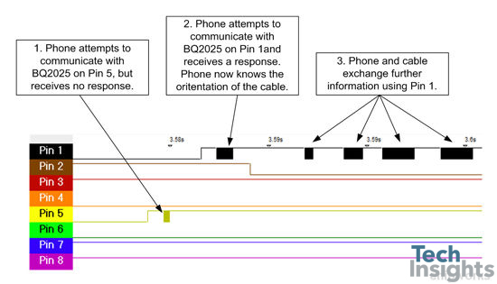
So, there are two pin choices for communicating with the cable. How does the phone figure out which pin to use? Simply put, it tries both. The figure below shows a signal capture taken when the Lightning cable is plugged into an iPhone 5. The phone first attempts to communicate with the cable on Pin 5, but receives no response. The phone attempts to communicate with the cable on Pin 1. This time, it receives a response. The phone now knows which way the cable was inserted.
Apple’s cross-connected cable pinout, combined with software running on the phone, ensures that the Lightning USB cable itself does not need any special hardware or other intelligence to allow it to be inserted upside-down (or right-side-up?).
Data Protocol
Data Protocol
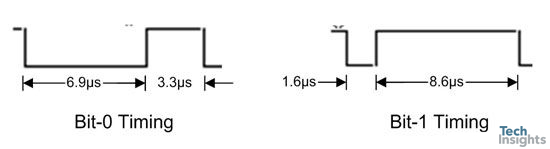
The data appears to use a similar one-wire protocol to that is used by the other BQ202x devices, but it does not conform exactly with respect to framing. The timing diagrams below show encoded bit 0 and bit 1 values as they appear on the data line. In both cases, it takes approximately 10.2 µs to transmit a bit. However, each byte is framed with a 12 µs delay. Taking this into account, the maximum communication rate is approximately 85 kilobits per second.
We have only discussed the communication rate between the phone and the BQ2025. The USB data rates are, of course, much higher. By the way, the USB data lines are connected to the red and brown signals of Figure 2.
Data Exchange
Here is where we can talk specifically about what we saw. Doing a truly complete systems review of any particular aspect of the cable is not in the blogging budget, but we can make a few interesting observations.
We’ve seen how the phone and cable can establish a conversation, but what do they talk about? We decoded several communication transactions and made some interesting discoveries. For example, the first byte in a transaction looks like a command byte from the phone (if the least significant bit is 0), or a response identifier from the cable (if the least significant bit is 1). The last byte in a transaction could be a CRC. This idea is described in the TI documentation for devices in the BQ family of parts. However, the command bytes that Apple uses are undocumented.
When we compare the captures for two different (but same model) Lightning USB cables, we noticed that the content of the last three data exchanges is different (i.e., the rightmost three black blobs in the figure above). In the first of those three exchanges, the cable returns 8 bytes of binary data. In the second and third exchanges, the cable returns a few binary bytes and a 16 character ASCII string. There doesn’t appear to be a key exchange, session establishment, or authentication. There doesn’t even appear to be a challenge-response sequence. The phone sends only a handful of bytes to the cable. The cable does most of the talking.
So there you have a sneak peek into some of the initial systems work we are doing on the Apple Lightning to USB cable. For those interested in more details inside this high volume part, we are producing a systems report on the cable and a circuit analysis on the BQ2025.